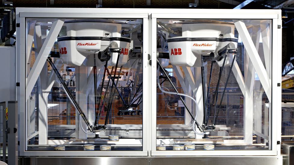
Three motors manipulate three parallelograms to move a platform in the X, Y, and Z directions.Ī fourth axis can be included for rotation, either by attaching a rotary actuator directly to the platform, or by adding a leg that extends from the center of the base to the center of the platform, with a rotating joint on the end. From a mathematics standpoint, the kinematics of a delta robot are relatively straightforward. These lower sections of the legs make up the three parallelograms that control the platform, constraining it to X, Y, and Z motion, parallel to the base. These legs are jointed (think of knees), with the lower sections consisting of two bars in parallel, and the lower end of each bar connected to the moving platform, which is also an equilateral triangle.


The base is essentially an equilateral triangle, with three legs connected to it-one on each side of the triangle-each moved by a small motor. This stems from their design, with a fixed base overhead and moving, jointed structures suspended from it, resembling a spider with spindly legs.ĭelta robots operate on the basis of three parallelograms connected to a stationary base above and a moving platform below. Note that the term “legs,” rather than “arms,” is typically used when discussing delta robots. For example, in an X-Y-Z Cartesian robot, the Y axis must support the Z axis, and the X axis must support both the Y and Z axes. In contrast, SCARA, 6-axis, and Cartesian styles are serial robots, meaning that each arm has to carry the next arm beyond it. Parallel vs serial robotsĭelta robots are a type of parallel robot, meaning that their motors and legs are connected mechanically in parallel, with each leg supporting only itself.

But there’s another robot design that is gaining prominence, especially in packaging and electronic assembly applications-the delta robot. Discussions of industrial robots typically focus on three types: Cartesian, SCARA, and 6-axis.


 0 kommentar(er)
